
Museum track lighting is a conservation instrument with an optical job. Every head on the rail is making two decisions at once: how much light the object receives over its lifetime, and where that light lands so the visitor can actually see it. Get only one of those right and you have either a forgotten object or a fading one. This guide covers both, with the numbers we use on site: the lux levels each material can take, the UV and IR limits that decide the source, the mirror-reflection geometry that decides the aiming angle, and the aiming and beam specifications that make a rail useful for twenty years of changing exhibitions.
New York is a useful reference point for all of it. Between the Metropolitan Museum of Art, the Frick, the Guggenheim and the Morgan, the city’s galleries solved most of these problems decades before anyone wrote a standard for them — and the answers they arrived at, from daylight filtering to track-rail geometry, are the same answers a small regional museum or a private collection still needs today.

Why museum lighting is a different problem from gallery lighting
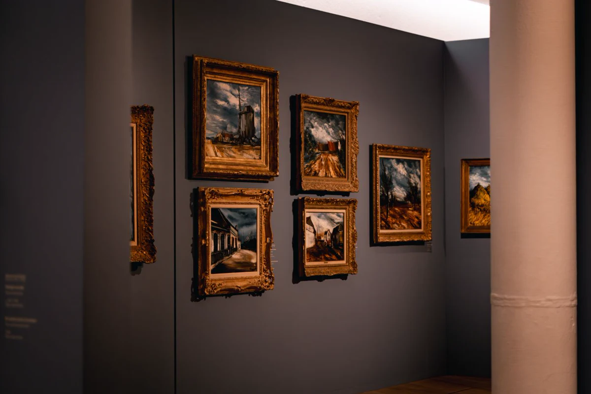
A retail lighting designer optimises for attention; a museum lighting designer optimises for exposure. The two use the same fixtures and the same physics, but they are solving opposite problems. In retail you want the object to shout, which means contrast, high output and no restraint. In a museum you want the object to be legible, which means controlling the total amount of light it receives over the whole exhibition period.
That is why museum lighting standards are written as budgets rather than as recommendations. Light is energy, and every photon that lands on a pigment breaks a small number of chemical bonds. The damage is cumulative and irreversible, and it does not announce itself: a watercolour that looks perfect in year three is noticeably paler in year fifteen. The conservator’s tool is not a brighter lamp but a lower total dose, and the lighting designer’s job is to hit the viewing target without spending more of the budget than the object can afford.
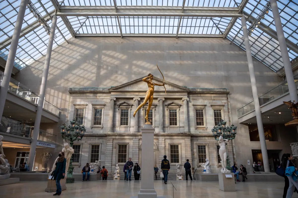
At the Metropolitan Museum of Art in New York, this is visible in the building itself. The Charles Engelhard Court is glazed, and daylight pours into the sculpture hall through the roof lantern and the facade windows — beautiful, and completely uncontrolled in UV terms. That is acceptable for marble and bronze and completely unacceptable for works on paper. The same building therefore uses quite different strategies metres apart, and the dividing line is the material, not the room.
If you are working on the gallery side rather than the conservation side, our art gallery lighting standards guide covers the same numbers from a specification-checklist angle, and museum lighting requirements: lux, CRI and UV sets out the standards themselves. This article goes further into the two things that actually get specified badly on site: the aiming geometry and the annual exposure budget.
Lux levels by material sensitivity — and the annual budget behind them
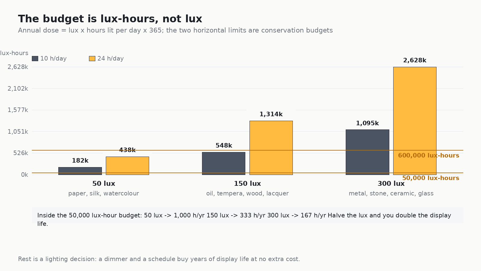
The lux figure everyone quotes is only half the specification. What conservators actually track is lux-hours: illuminance multiplied by hours of exposure, summed over a year. Fifty lux sounds safe, but fifty lux on an object lit ten hours a day, seven days a week, is 182,500 lux-hours a year — nearly four times a 50,000 lux-hour budget. This is why two galleries can both claim “we light to 50 lux” and get completely different fading rates.
The practical relationship is simple and worth stating plainly: halve the illuminance and you double the display life. That single sentence is the entire argument for dimming, for motion-triggered lighting, and for exhibition rotations.
| Material category | Examples | Max illuminance | Annual budget | Permitted hours |
|---|---|---|---|---|
| Highly light-sensitive | Watercolour, paper, silk, textiles, dyed leather, most photographs | 50 lux | ~50,000 lux-hours / year | ~1,000 h / year |
| Moderately sensitive | Oil and tempera paintings, wood, lacquer, bone, ivory, horn | 150–200 lux | ~150,000–600,000 lux-hours / year | ~1,000–4,000 h / year |
| Low sensitivity | Metal, stone, ceramics, glass, enamel, jewellery (metal only) | 300 lux | Not time-limited | Unrestricted |
| Mixed object | An oil painting with a pastel or gouache passage, a textile-mounted panel | 50 lux — governed by the most sensitive component | ~50,000 lux-hours / year | The ensemble follows the weakest material |
Two consequences follow. First, the lux limit is set by the most sensitive component of a composite object, which is why a painting with a watercolour underdrawing revealed at the edge goes to 50 lux rather than 200. Second, the lux you measure at the object is not the lux the lamp makes: the same 20 W head delivers roughly 150 lux to a small canvas with a narrow optic and close to nothing with a wide one from the same distance. Beam control is therefore not a stylistic choice — it is the mechanism by which the conservation target is actually met.
The number almost nobody specifies: the annual rest period
If an object has a 50,000 lux-hour annual budget and the gallery runs a 50 lux display for eight hours a day, it will exhaust that budget in about 125 days. The remaining 240 days are not optional — they are the conservation plan. Institutions handle this in three ways, and the most useful one for a small museum is the cheapest:
- Rotate the object. Bring it out for a defined season, then substitute a different work from storage. The budget is spent deliberately rather than accidentally.
- Motion-trigger the head. A presence sensor that lifts the head to display level only when a visitor is in front of it can cut exposure by 60–80% in a low-traffic room, and it is invisible to the visitor when it works properly.
- Dim rather than switch. Running a 150 lux display at 80 lux costs 0.53× the dose and is still perfectly viewable for most oil paintings. The trade is subtle — at 80 lux the darker passages start to collapse and visitors lean in.
UV, IR and blue light: what the source has to do
Damage from light splits into three channels, and modern LED sources handle two of them almost for free.
UV: below 10 µW/lumen, and effectively zero
Ultraviolet is the most damaging part of the spectrum per unit of energy. It fades dyes and pigments, yellows paper and varnish, and embrittles organic fibres. The conventional limit is under 10 µW/lumen on the object surface, and for the most fragile works the practical target is zero measurable UV.
Halogen and fluorescent sources needed UV-filter sleeves and heat-absorbing glass to get anywhere near that, and the filters were always a maintenance item. A well-specified LED emits negligible UV as a property of the source itself, so the specification question changes from “which filter” to “which fixture”. Ask for a spectral power distribution in the 300–400 nm band rather than a claim on a datasheet; on a quality museum-grade LED it will be flat at the noise floor.
IR: keep the object’s surface temperature from rising at all
Infrared is a heat problem rather than a chemical one. It raises the surface temperature of the object, which drives drying, dimensional movement and micro-cracking, and in the worst case lifts a paint film off its ground. The target is that the object’s surface temperature does not rise measurably above ambient — ideally under 1 °C. LEDs produce very little radiant heat in the beam, and the heat they do produce is at the back of the fixture and goes into the plenum; on a properly designed head, radiant heat at the object is not a design constraint.
Blue light: measured as relative risk, not as a scare figure
The short-wavelength, high-energy end of the visible spectrum does measurable damage on its own, without any UV at all. This matters because a 4000 K LED puts considerably more energy into the 400–500 nm band than a 2700 K source of the same lumen output. The rule for light-sensitive material is therefore: specify the warmest colour temperature the exhibition can tolerate, then use high colour rendering to recover the colour that the warm temperature costs you.
| Damage channel | Target | How it is met | What to ask a supplier for |
|---|---|---|---|
| UV radiation | < 10 µW/lumen at the object | LED source, uv-free by construction; no filter sleeves to maintain | Spectral power distribution, 300–400 nm band |
| IR radiation | Object surface rise < 1 °C | LED with the driver heat path away from the beam and into the plenum | Beam heat figure, or a measured surface temperature test |
| Visible blue light | As warm as the exhibition allows | 2700–3000 K for sensitive material; never use 4000 K on paper or textile | SPD across 400–500 nm, not just CCT |
| Total dose | Within the material’s lux-hour budget | Dimming, scheduling, rotation, presence control | Dimmable driver to 1% with no colour shift at the bottom |
CRI, R9 and why the colour temperature is a conservation decision
Colour rendering is usually discussed as an aesthetic question, but in a museum it is also a conservation lever. A 2700 K source at CRI 95 does less blue-light damage than a 4000 K source at CRI 95, and it renders the warm earths and varnishes of older paintings more sympathetically. If the colour does not survive the warmer temperature, the problem to fix is the rendering index, not the colour temperature.
Three figures matter, and the second two are the ones that get quietly dropped:
- Ra (general CRI): 90 is the usual minimum, 95+ is what colour-critical displays actually need.
- R9 (deep red): must be above 90 for painting, textiles, skin tones and lacquer. A fixture claiming Ra 95 with R9 60 will render reds muddy, and it will do it on exactly the objects museums care most about.
- SDCM ≤ 3: the colour consistency between the individual heads on one rail. This is where budget fixtures fail. Two heads marked 3000 K from different production batches can be visibly different on the same wall, and nothing in the CRI figure warns you.
The practical check is to look at a sample rail with all the heads energised on a white wall before the order is placed. If you can see the difference between individual pools of light, the installation will look wrong for its whole life and no amount of aiming will fix it.
Beam angle is a specification, not a preference
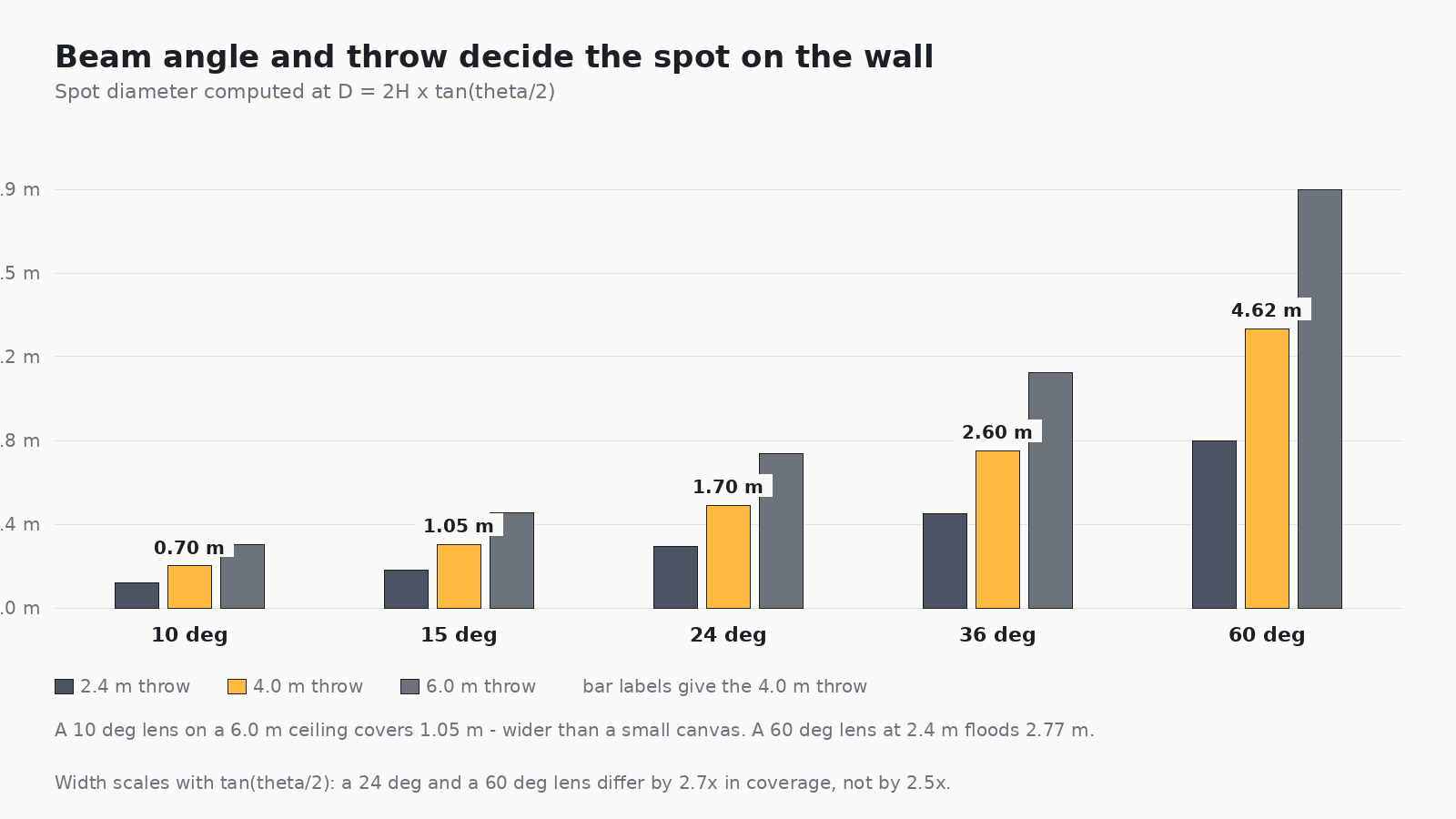
Every lighting plan asks the same question in different words: how wide is the pool of light on the object? The answer is arithmetic, and getting it wrong is the single most common reason a museum installation looks amateur. The relationship is:
D = 2 × H × tan(θ / 2)
where D is the spot diameter at the object, H is the distance from the lens to the object surface, and θ is the beam angle.
Two things follow from that formula, and both are counter-intuitive enough that they get missed:
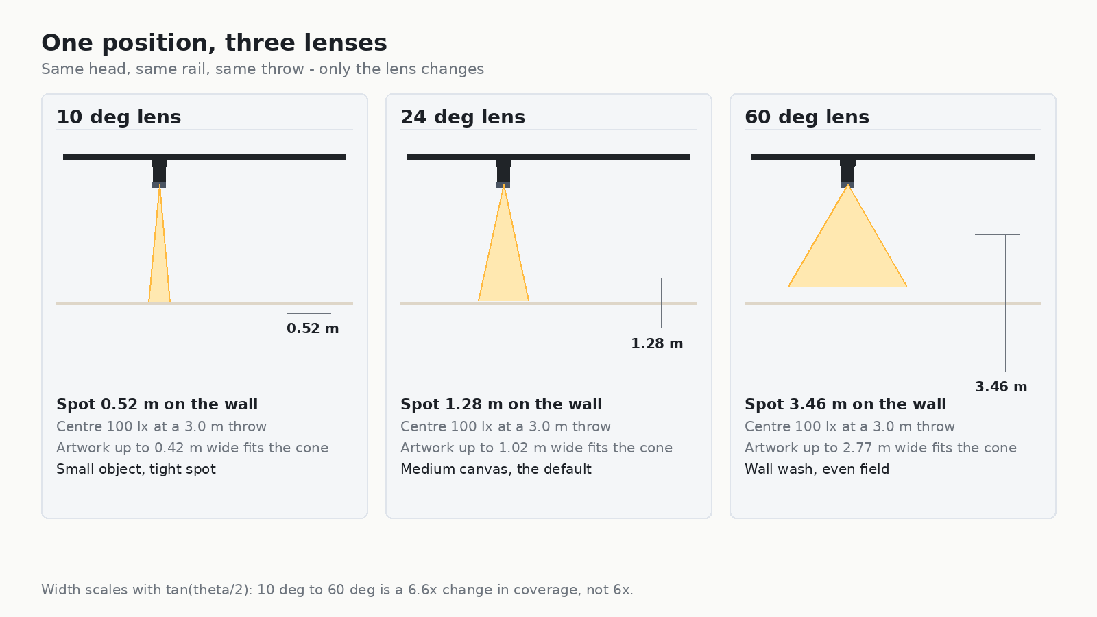
- Width scales with tan(θ/2), not with θ. A 60° lens covers only 2.7× the width of a 24° lens, not 2.5×, and the gap widens as the angles get smaller. Going from 10° to 60° is a 6.6× change in coverage, not 6×.
- Doubling the throw doubles the spot but quarters the illuminance. A head moved from a 2.4 m throw to a 4.8 m throw spreads over four times the area, so its centre illuminance falls to a quarter. If you specified the head for 150 lux at 2.4 m, it delivers 37 lux at 4.8 m.
The working ranges we specify for museum work
Across a museum project, four optic ranges cover almost everything, and a rail that offers all four from one head family is worth more than a rail that is marginally cheaper per head:
| Optic | Beam angle | What it is for | Typical throw |
|---|---|---|---|
| Narrow spot | 6°–15° | Small bronzes, coins, jewellery, seals, detail accents | 2.5–4 m |
| Projector / framing | 18°–36° adjustable, with shutters | Anything with a hard edge: a rectangular canvas, a triangular vitrine, a wall-mounted panel | 3–6 m |
| Flood accent | 24°–38° | The default for paintings on a hanging rail | 3–5 m |
| Wall wash | asymmetric, e.g. 25°×75° | A whole wall of framed works, an even background field, a text wall | 1.5–3 m from the wall |
The whole wall, and where the natural light goes
New York’s older galleries are a catalogue of strategies, and one of them is worth copying. The Guggenheim’s rotunda is a single continuous spiral, which means the “wall” is not a wall at all — it is a curve of changing height, and the light has to hold its angle as the visitor walks. The Frick’s smaller rooms do the opposite: flat walls, a defined picture height and a rail that stays in one place for decades. The Morgan approaches it from the third direction, mixing a glazed court with controlled rooms around it.
The lesson for a new project is that if the architecture is going to change the geometry, the lighting system has to be reconfigurable rather than fixed. This is the argument for track over recessed downlights in a museum: the rail can follow a vaulted or curved ceiling, and the heads can be re-aimed when the hang changes. A recessed grid is a plan for one exhibition.
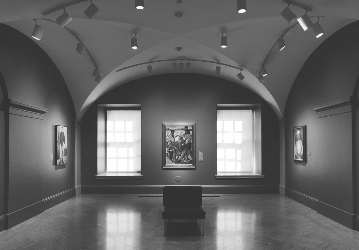
Daylight is the other half of the problem, and it is the half that is most often left unmanaged. A glazed court or a skylit top-floor gallery delivers unfiltered UV and an illuminance that swings by orders of magnitude across a day. If the collection is under it, the case does the work: a vitrine with a UV-absorbing glazing and a controlled head inside is a complete lighting solution, and the daylight becomes room ambience rather than object exposure.
Aiming: the 30–40 degree rule and the geometry behind it
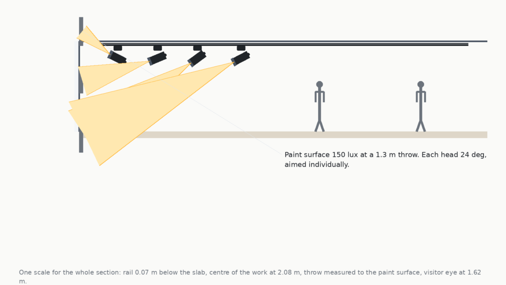
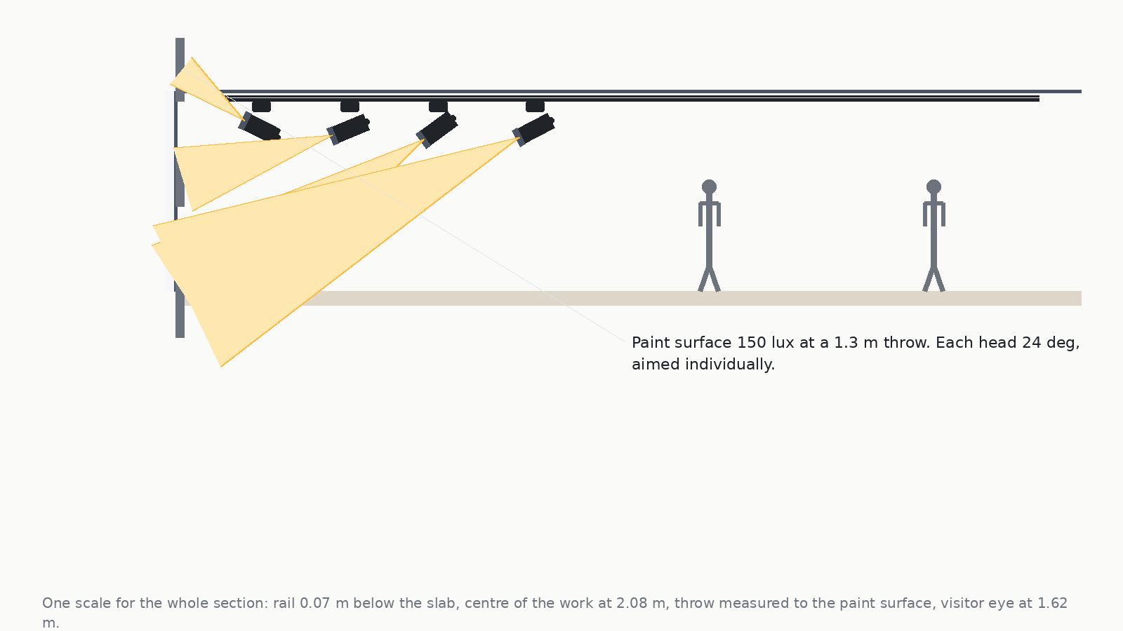
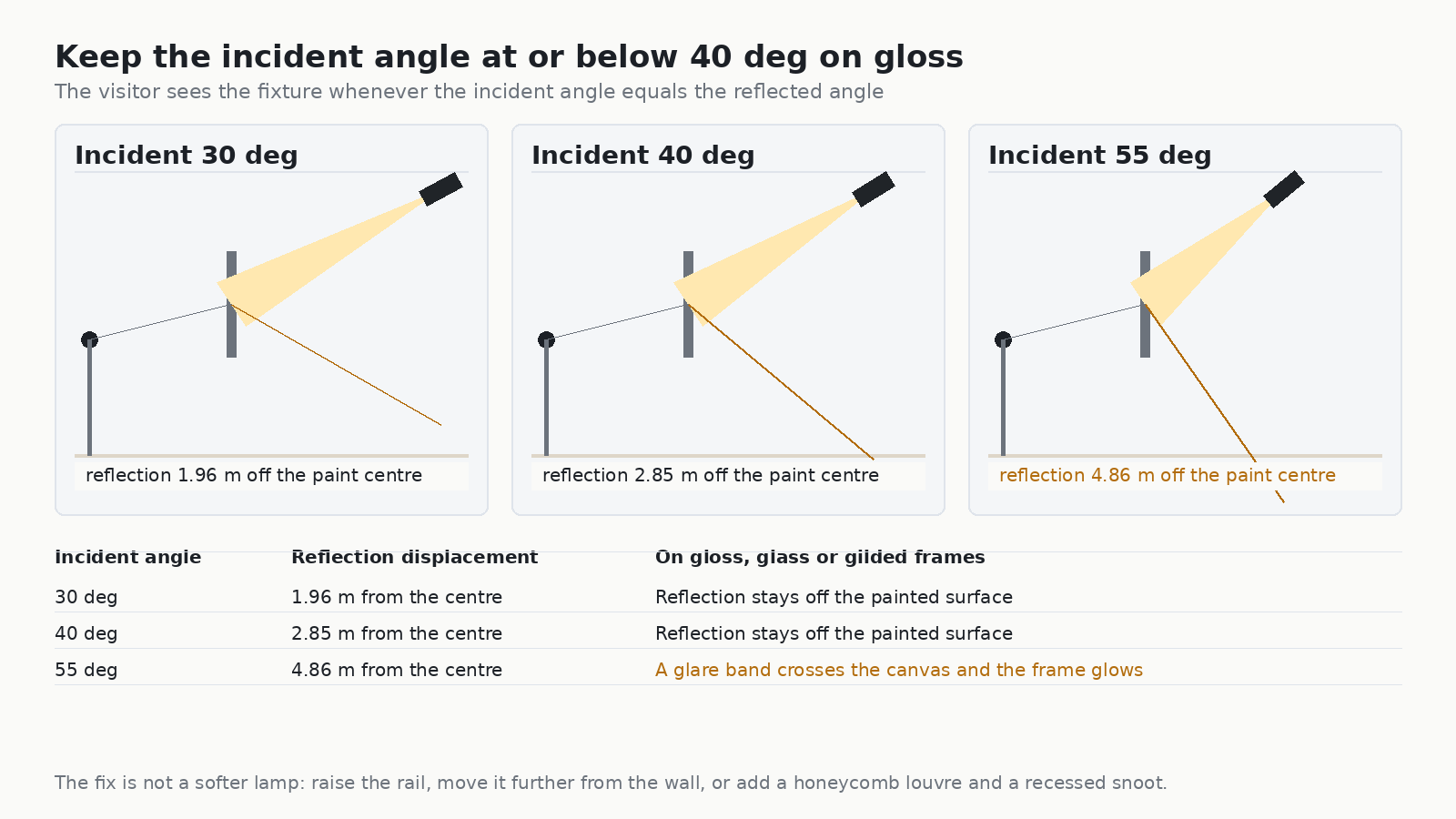
Most guidance tells you to aim heads at 30° to the surface of the wall. That number is not arbitrary, and it behaves like a cliff rather than a slope: the glare the visitor sees is a function of the incident angle, and it gets much worse very quickly above about 40°. Working out why takes one drawing.
When light strikes a glossy surface — varnish, glazing on a frame, polished stone, a gilt frame — the surface behaves like a weak mirror: the incident angle equals the reflected angle. That reflection is faint, but it is aimed somewhere, and if it lands where the visitor’s eye happens to be, the visitor sees the fixture reflected in the surface rather than the picture. The horizontal displacement of that reflection from the centre of the object is a simple expression: offset = throw × tan(incident angle).
At a 3.4 m throw, a 30° incident angle puts the reflection almost 2 m off the centre of the work, which in a normal gallery is behind the visitors’ heads. At 55° the same geometry puts it nearly 5 m off centre — and because a gallery is a corridor, that means it lands on the opposite wall, and every visitor walking through the room crosses the sight line. On an unglazed matte oil painting, none of this applies. On anything with a surface sheen, it applies to everything.
Solving the glare with geometry rather than with a softer lamp
There are three places the problem can be fixed, and the third is the one people forget:
- Raise the rail. Moving the rail up and away from the wall reduces the incident angle for the same object position. On a 3.4 m throw, a head moved from 55° to 40° takes the floor-standing visitor out of the sight line entirely.
- Move the rail out from the wall. Increasing the horizontal offset does the same thing in the other axis, at the cost of needing a wider beam to cover the object.
- Change the optics. A recessed snoot physically blocks the sight line into the lens; a honeycomb louvre reduces the light leaving at high angles. Both cut glare without touching the aim, and both are tool-free accessories on a properly designed track head.
The vertical aiming sequence: aim to the top edge, then check the bottom
Aiming a single head at a single object is a four-step procedure, and the fourth step is the one that gets skipped. Work in this order and the result is predictable:
- Set the vertical tilt by the top edge of the object, not by its centre. Aim the beam centre roughly 60–70% of the way up the object. Aiming at the centre is what produces the classic dark-top, hot-bottom pool of light.
- Check the bottom of the beam against the bottom of the object. If the object is taller than the spot you have, you need either a wider optic or a taller throw — you cannot fix it with aim.
- Set the beam edge, not the beam centre. The falloff at the edge of a spot is not a hard line. Set the visible illuminated edge slightly inside the object’s edge so the wall does not have a scalloped halo around it.
- Walk the viewing distance and check the glare. Stand where the visitor will stand, at the closest approach the room allows, and look at the object. If you can see the lens or its reflection, re-aim before you move on.
Rail layout: one row or two, and where the heads go
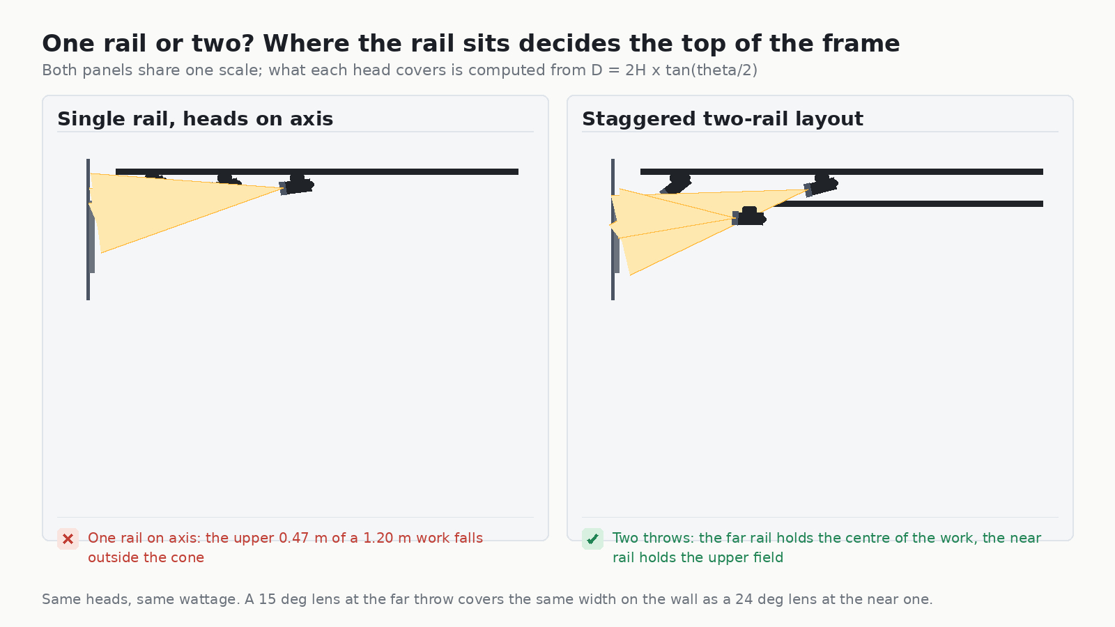
Layout is decided before any head is aimed, and the decision is driven by the ratio between the height of the work and the width of the spot you can get at a workable throw. On a normal 3 m ceiling, a single row of heads on the rail at a 3.4 m throw with a 24° lens gives you a spot about 1.4 m wide. That is wider than a typical canvas and shorter than a typical canvas is tall, so the spot covers the width and misses the top.
The two ways out are to use a taller throw with a wider optic from further back, or to add a second row of heads. The second row is the more useful answer in a mixed exhibition, because it lets the near rail hold the upper field on a lower throw while the far rail holds the centre of the work:
Spacing heads along the rail
Set the spacing from the spot diameter, not from the object width. Two adjacent spots should just touch or slightly overlap — a 10% overlap is the working figure — which at a 3.4 m throw with a 24° lens means roughly 1.28 m between head centres. Space them wider and you get dark bands between objects; space them closer and you double the load on the objects at the overlap.
Fitting track into a ceiling that was not designed for it
Older galleries are full of ceilings that resist mounting: baffled acoustic decks, historic plaster, timber coffers, exposed concrete. The mistake is to assume a rail has to be fixed to the finish. In practice a track run can be:
- Surface-mounted to the slab where the finish can be penetrated and the depth is available.
- Suspended on rods to reach a usable mounting plane below a baffle or coffer, which also lowers the rail and improves the incident angle as a side effect.
- Recessed into a plaster reveal in a new-build gallery, which is the cleanest visual result and the least flexible to change later.
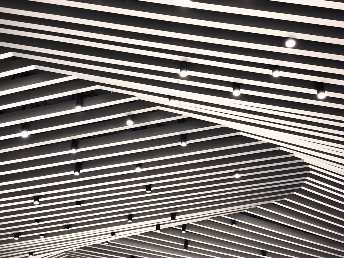
Whatever the mounting, verify three things before the heads go on: that the rail body is straight over its whole length when viewed from the floor, that the structure above it is rated for the total weight of rail, heads and any accessories, and that every head can reach its object without the yoke binding. A rail that is 20 mm out of true over 6 m is visible from the gallery floor even though it looks fine from a ladder.
The hardware that does this work
The fixtures below are the ones we would put on a museum rail, and each one exists because of a specific requirement in this article. All of them run on the same single, three-circuit or three-circuit DALI profile, so a gallery can mix them on one rail without any adapter question.
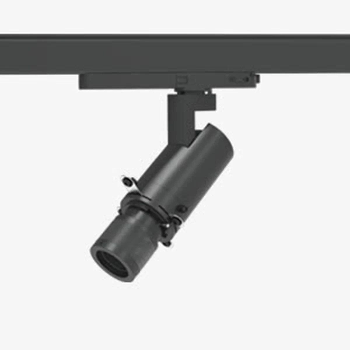
IMAX-Projector 10–20 W — the framing head
The framing projector is the fixture that museum work is actually built around, and the IMAX-Projector is the one we specify most often for it. A 21–34° adjustable beam (18–30° and 24–36° on the 20 W) with a framing mechanism that cuts the beam into a rectangle or a triangle is what lets you light a canvas edge-to-edge with no spill onto the wall behind it. The head swivels 360° horizontally and 90° vertically without dead angle, and the optical system is designed to collect the beam tightly so there is no stray light in a dark room — which is what the UGR < 6 figure is telling you. Colour filters and custom logo patterns are available for gobo work.
The rest of the rail
- IMAX-Projector 10–20 W — the framing head described above; the default for anything with a defined edge.
- IMAX-Zoomable 10 W — a continuous 6°–50° range in one head, with ±5% beam control. Useful where the same rail has to serve objects of very different sizes between rotations.
- IMAX-Zoomable 15–30 W — 10°–70° sharp or 15°–70° soft, CRI 90+/95+, up to 1,828 lm; self-dimming 0/1–10 V built in, which is what makes the annual dose budget controllable without adding a control system.
- IMAX-Standard 15–30 W — fixed 15°/24°/38°/60° optics, >100 lm/W, tool-free honeycomb or cross-louver anti-glare accessories. The workhorse for the general gallery where the optics do not need to change.
- OVEGA-Wall Washer 10–20 W — an asymmetric 25°×75° distribution that washes a wall evenly with no visible light edge, which is what a wall of framed prints or a text wall needs instead of a row of spots.
- OVEGA-Projector 10–25 W — a compact framing projector with 20°–40° adjustable beam and a movable ring that switches between a hard and a soft beam edge, for tighter ceiling voids.
- CADIO 20–30 W — >100 lm/W with tool-free interchangeable reflectors and a honeycomb anti-glare accessory; a sensible general accent head at a lower cost per position.
- MOVIA 30 W — motorised 360° pan, ±140° tilt, 18°–60° zoom and 2700–6000 K tunable white on Casambi, with stored scenes. The answer where the ceiling is out of reach or where the lighting has to change between a daytime and an evening configuration.
Where the track is being used as an architectural line rather than only as a mounting device, our linear lighting systems and the SLEM 2.4 in linear light system give a continuous run with modular L, X and T connectors — useful for the ambient layer over a circulation route. The full track light range and the cylinder light range cover the rest of the portfolio.
Certification and compliance
For a public building the fixture certification is not negotiable, and it is worth checking early because it is hard to change later. Look for ETL or cETL listing for the luminaire and the track system as a matched assembly rather than for the head alone — an unlisted adapter on a listed rail is a common and avoidable finding. In North America the relevant standards are UL 1574 for track lighting systems, and for a public assembly space you should expect to show the listing at inspection. Our ETL vs cETL certification guide explains what the two marks mean and when each applies.
Two other requirements are common in public galleries and easy to forget: dimming must not shift colour at the bottom of the range (check the fixture at 1% as well as at 100%), and flicker must be low enough not to be visible. Flicker is a comfort problem rather than a conservation one, but in a quiet room under a 95+ CRI source it is the defect visitors notice.
Commissioning: what to check before the opening
Aiming is a commissioning task with a deliverable, not a finishing touch. The checklist below is the one we hand over with an installation, and each line is measurable:
| Check | Target | Instrument |
|---|---|---|
| Illuminance at each object | Within the material category’s limit; uniformity Emin/Emax ≥ 0.7 across the object | Calibrated lux meter at the object surface, held parallel to it |
| Colour rendering | Ra ≥ 90 (95+ for colour-critical), R9 > 90, SDCM ≤ 3 across the rail | Datasheet plus a visual comparison of all heads energised on a white wall |
| Glare from the viewing position | No lens or reflection visible at the closest approach the room allows | Walk the room and look; this one cannot be measured from a drawing |
| UV at the object | < 10 µW/lumen; ideally at the meter’s noise floor | UV meter, or the fixture’s spectral power distribution in the 300–400 nm band |
| Annual dose | Recorded per object as lux × scheduled hours × 365, inside budget | Scheduler settings plus the lux reading; keep the arithmetic on file |
| Dimming behaviour | No visible colour shift from 100% to 1%; no audible driver noise in a quiet room | Dim the rail and listen and look |
Record the final aim state: for each object, the head position on the rail, the tilt angle, the optic fitted, the dimmer level and the measured lux. That record is the only thing that travels with the installation. Ten years later, when a curator asks why one painting looks warmer than the one beside it, the answer is in that sheet — and the rail can be re-aimed from it in an afternoon instead of a week.
Common mistakes on museum track installations
- Aiming everything at the same tilt. Wall heights, object heights and rail offset all vary along a run. A uniform tilt produces a uniform look, but not a correct one.
- Specifying lux and ignoring hours. A 50 lux display running every hour the building is open exhausts a highly sensitive object’s annual budget in a quarter of the year.
- Choosing colour temperature by eye in a lit room. Colour temperature judgements made under mixed light are wrong more often than not. Compare warm and neutral on the actual object.
- Accepting Ra 95 without R9. The metric that matters most for paintings, textiles and gilt is the one most often left off the datasheet.
- Mixing heads from different production batches. Without an SDCM ≤ 3 guarantee across the order, the mismatch will be visible on the wall, not on the sample.
- Installing the rail too close to the wall. A short horizontal offset forces a steep incident angle, and a steep incident angle is what produces mirror glare on anything with a sheen.
- Leaving no spare capacity on the rail. A rail specified exactly for the current hang has no position left for next year’s exhibition, and the fix is a new circuit rather than a new head.
Frequently asked questions
What lux level should museum track lighting deliver?
It depends on the material. Highly light-sensitive works — watercolour, paper, silk, textiles and most photographs — take 50 lux. Moderately sensitive works such as oil and tempera paintings, wood, lacquer and ivory take 150–200 lux. Low-sensitivity material such as metal, stone, ceramic and glass can go to 300 lux. A composite object follows its most sensitive component. Always use the lowest level that still lets the object be seen truthfully, and set the limit by annual lux-hours rather than by instantaneous lux alone.
How much UV should museum lighting have?
Under 10 microwatts per lumen at the object surface, and effectively zero for the most fragile works. A well-specified LED is UV-free by construction, so the requirement is met by choosing the source rather than by adding filter sleeves. Ask for the spectral power distribution in the 300–400 nm band rather than a claim on a datasheet.
What is the 30 degree rule in museum lighting?
It is an aiming guideline: keep the incident angle on the object at or below 30–40 degrees to the wall surface. The number comes from mirror-reflection geometry. On a glossy surface the incident angle equals the reflected angle, so the reflection of the fixture lands at a horizontal offset of throw × tan(incident angle) from the centre of the object. At a 3.4 m throw, 30 degrees puts that reflection about 2 m off centre, behind the visitors; 55 degrees puts it nearly 5 m off centre, which in a gallery corridor means every visitor crosses the sight line.
How wide should the beam angle be for museum track heads?
Match the beam to the object using D = 2H × tan(θ/2), where H is the throw and θ the beam angle. In practice: 6–15 degrees for small objects and detail, 18–36 degrees with a framing shutter for anything with a defined edge, 24–38 degrees as the default for paintings on a hanging rail, and an asymmetric wall-wash optic for a whole wall of framed works. Remember that width scales with tan(θ/2), so a 60 degree lens covers 2.7 times the width of a 24 degree lens, not 2.5 times.
Should I use track lighting or recessed downlights in a museum?
Track, in almost every case where the collection changes. Track gives individual aiming, reconfigurability without rewiring, glare control through accessories and precise beam shaping, which are exactly the four things a museum needs and a downlight grid cannot provide. A recessed grid is a plan for one exhibition; a rail is a plan for the next twenty years. Recessed fixtures make sense for circulation, back-of-house and ambient over a route, not for the display wall itself.
How many heads do I need on a rail, and how far apart?
Set the spacing from the spot diameter rather than from the object width. Two adjacent spots should just touch or slightly overlap — a 10% overlap is the usual figure, which means spacing equal to about 0.9 times the spot diameter. At a 3.4 m throw with a 24 degree lens that is roughly 1.28 m between head centres. Then allow spare capacity on the rail: a run specified exactly for the current hang has nothing left for the next one.
Can I retrofit museum heads onto an existing track rail?
Usually yes, but only if the heads match the rail family. Cross-family adapters exist but must match the slot geometry and the contact spacing of the rail in front of you, and getting that wrong is the most expensive mistake in a retrofir. Identify the rail first — our guide on how to identify H, J or L track sets out the four measurements that settle it — and confirm polarity with a meter before anything is energised.
Does a warmer colour temperature really reduce damage?
Yes, for light-sensitive material. A 2700 K LED puts less energy into the 400–500 nm band than a 4000 K source of the same lumen output, and that band does measurable damage on its own without any UV at all. The practical rule is to specify the warmest colour temperature the exhibition can tolerate and then use high colour rendering — Ra 95+ with R9 above 90 — to recover the colour that the warm temperature costs you.
Specify the exposure before you specify the fixture
The order of work matters more than any individual number in this article. Decide first what each object is allowed to receive over a year, in lux-hours. Then choose the source that can deliver it without UV or IR damage. Then work out the geometry — throw, beam angle, incident angle and rail position — that puts that light exactly on the object without glare. The fixture is the last decision, not the first, and it is the easiest one to change.
If you are mid-project and would rather work the numbers with us than alone, talk to the Encore specification team with the object list, the ceiling height, the rail offset and the viewing geometry. If the project is going out to tender, our track lighting RFQ guide sets out the specification envelope a supplier needs, and our museum track lights vs ordinary spotlights comparison covers the source-level argument in more depth.
Further reading: the National Park Service Conserve O Gram on museum lighting, the Getty Conservation Institute conservation publications, and the U.S. Department of Energy solid-state lighting programme.