
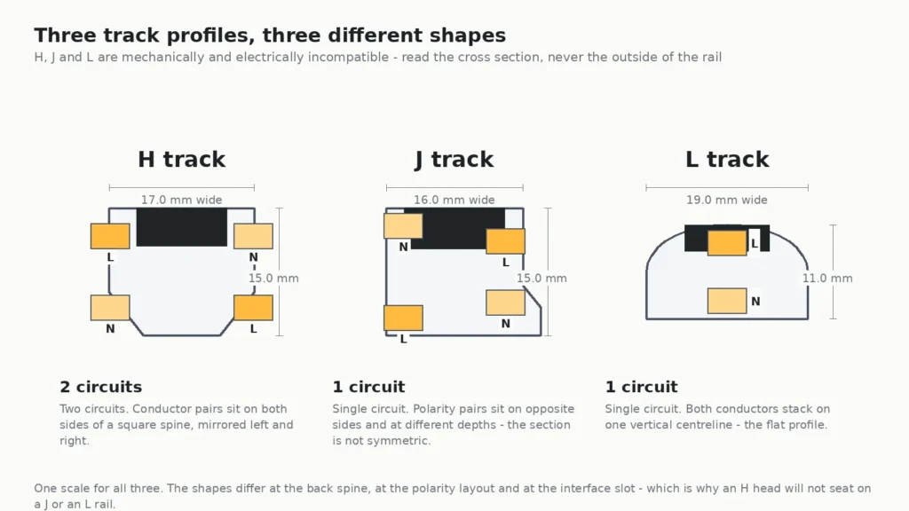
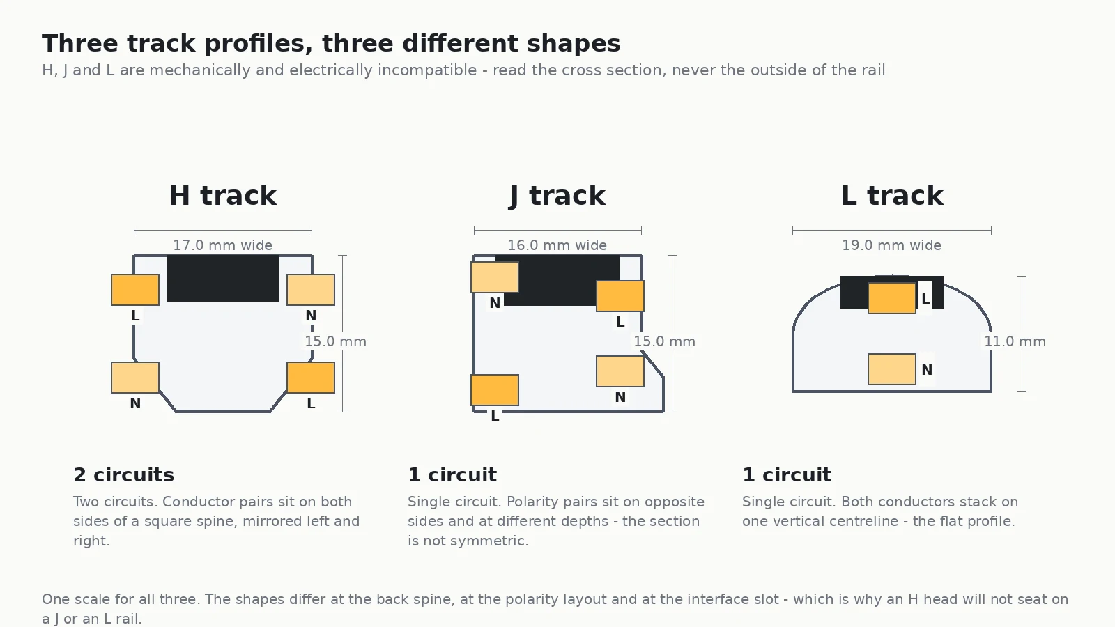
H, J and L are three different track profiles, not three brands of the same thing. The letters come from the three North American systems that dominated the market for decades, and each one was cut to a different cross section: different overall proportions, a different back spine, a different number of conductors and — the part that actually stops you — a different position for those conductors inside the rail. That is why an H head will not seat on a J rail, and why guessing from the outside of a rail is the single most expensive mistake in a track retrofit.
This guide is the method we use on site. You will identify an unknown rail from four measurable features, confirm it with a tape and a meter, and order a head that seats on the first attempt. No brand-name guessing, no forcing adapters.
If you are still choosing a system rather than identifying one, start with our commercial track lighting guide for system selection, and magnetic track lighting vs traditional track lighting if you are weighing a low-voltage rail against a line-voltage one. This article assumes the rail is already on the ceiling and you need to know what it is.

What H, J and L actually refer to
The three letters are shorthand for the three profile families that became the de facto standards in North America. Each was engineered as a complete system — rail, connectors, feed fittings, end caps and heads — and each solved the same problems a different way. Because they were designed before any cross-brand standard existed, compatibility was never the goal.
The practical consequence is simple and worth stating plainly: H, J and L are mechanically and electrically incompatible with each other. The rail will not accept another family’s adapter, or worse, it will accept it and fail to make reliable contact. Adapter kits exist for the common cross-family cases, but they have to be matched to both the slot geometry and the contact spacing — which means you need the section identification first regardless.
| Feature | H family | J family | L family |
|---|---|---|---|
| Circuits in the standard profile | Two | One | One |
| Conductors in the standard profile | Four (two pairs) | Two to four, depending on the variant | Two |
| Conductor layout | Pairs set side by side on both sides of the spine, mirrored | Pairs on opposite sides and at different depths — the section is not symmetric | Both conductors stacked on one vertical centreline |
| Interface slot silhouette | Chamfered shoulders, wider slot | Stepped shoulders, single-side flag | Round shoulders, narrow slot |
| Typical use | Larger retail and hospitality jobs that want two switched circuits on one rail | Single-circuit residential and light commercial retrofits | Low-profile runs where the rail should nearly disappear |
| Cross-family fit | No | No | No |
Note the second row carefully: variants exist inside every family. A single-circuit H rail and a two-circuit H rail both exist, and so do single-circuit J rails with only two conductors. The family is decided by the geometry of the section, not by the conductor count alone. Use the conductor count to narrow the field, then confirm with the shape.
The four features that decide the family
You do not need a datasheet, a brand name or an internet connection. Four things on the cross section decide it, and you can read all four with a torch and a tape. This is the order we work in, because each check eliminates options rather than adding them.
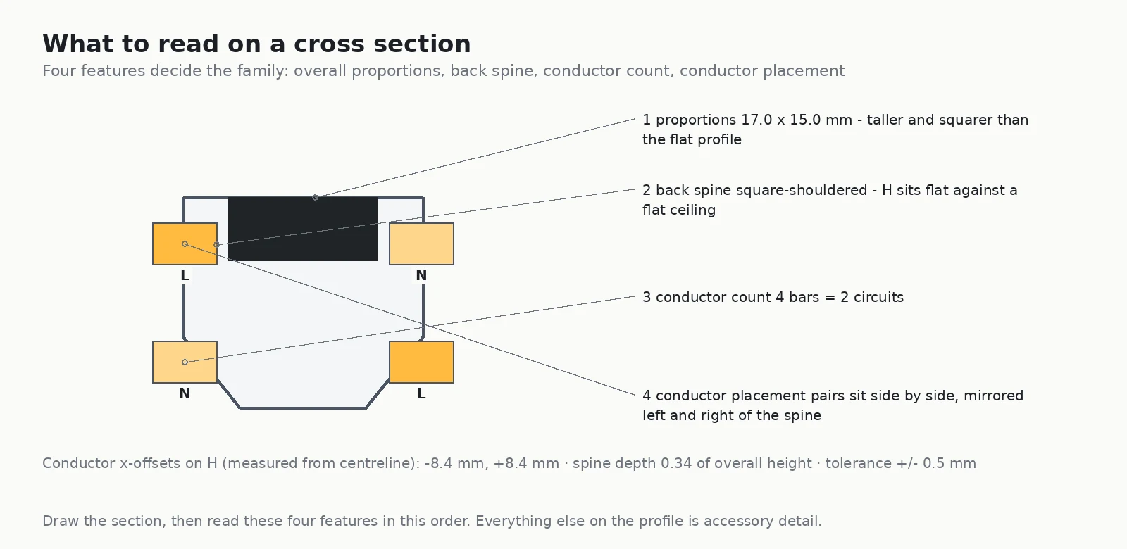
1. Overall proportions
An H section is close to square in silhouette, roughly 17 mm wide by 15 mm deep on the standard profile. A J section is a similar height but slightly narrower. An L section is the outlier: noticeably wider and distinctly shallower, because it was designed to be visually quiet. Widths across the families differ by only a few millimetres — inside a normal ± 0.5 mm extrusion tolerance band — so proportions tell you which family you are looking at, but they will not settle it on their own.
2. The back spine
The spine is the part of the extrusion that lands against the ceiling, and each family finished it differently. The H profile carries square shoulders with a chamfered transition to the head; the J profile is asymmetric, with a single-side flag that sticks out past the body; the L profile has round shoulders that form a continuous shallow curve. Look at the top third of the section and the family is usually obvious before you count anything.
3. Conductor count
Switch off the circuit, lock it out, remove the heads, and count the bare bars with a torch. Four bars means two circuits if the rail is an H, and it means one circuit with polarity pairs on both sides if the rail is a J — the count alone does not separate them, which is exactly why step four exists. Two bars means single circuit, either J or L.
4. Where the conductors sit — the decisive test
This is the check that actually settles it, because it is the difference the head has to physically reach. Drop a plumb line through the centre of the section and measure the horizontal offset of each conductor from that line.
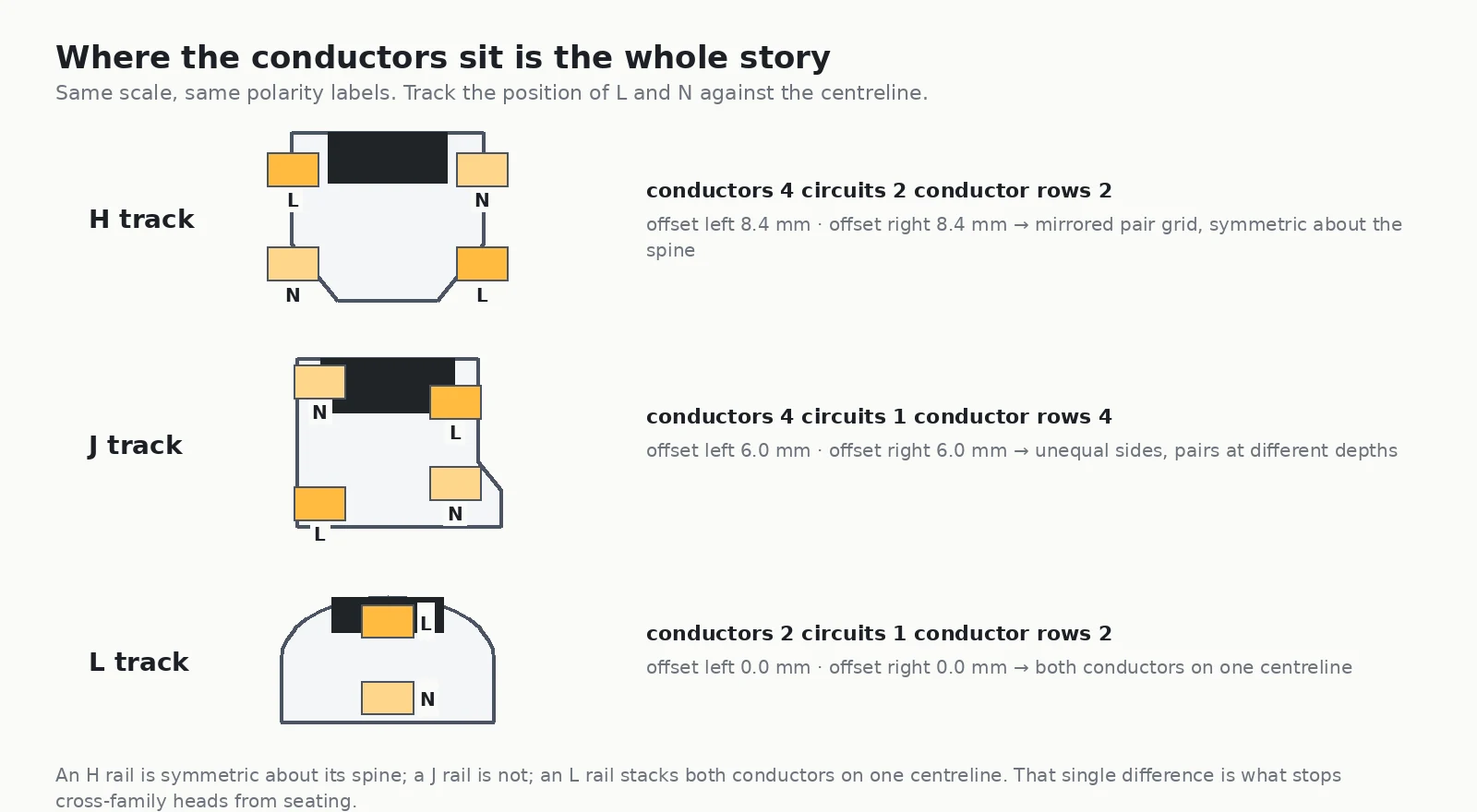
- H: conductors sit in a mirrored pair grid, roughly 8 mm to the left and 8 mm to the right of the centreline, with two conductor rows. The section is symmetric about its spine.
- J: conductors sit at roughly 6 mm on both sides, but at different depths on each side and across four separate rows. The section is not symmetric. This is the tell.
- L: both conductors sit on the centreline itself, offset 0 mm horizontally, stacked above and below each other. There is no lateral offset to measure at all.
On paper the distinction is obvious. On a ceiling it is not, which is why the tape comes out before the order does.
Identify an unknown rail on site, in four checks
This is the sequence to run from a ladder. Work top to bottom and stop as soon as the answer is unique.
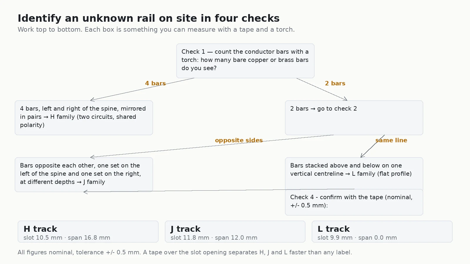
Check 1: count the bare bars
Power off, lock out, pull the heads. Count the visible conductor bars. Four bars sends you to the H-or-J branch; two bars sends you to the J-or-L branch.
Check 2: find whether the section is symmetric
Four bars arranged in mirrored pairs, left and right of the spine, is an H. Four bars spread across opposite sides at different depths, with the section visibly lopsided, is a J.
Check 3: for two-bar rails, look at the centreline
Two bars opposite each other, one set on the left of the spine and one set on the right, at different depths: J. Two bars stacked vertically on one centreline: L.
Check 4: confirm with the tape
Measure the slot opening with the heads removed. Nominal figures on the standard profiles are around 10.5 mm for H, 11.8 mm for J and 9.9 mm for L, with the widest contact span at roughly 16.8 mm, 12.0 mm and 0 mm respectively — the L figure being zero because its conductors share one vertical axis. These are nominal values at a ± 0.5 mm tolerance, so treat them as a cross-check on checks one to three, never as the first test. Worn or repainted extrusions will read differently from the drawing.
Confirm polarity before anything goes on the rail
Identification tells you which head to order. It does not tell you which bar is which, and on a retrofit nobody knows what the last electrician did. Confirm it yourself, in this order, rather than trusting a label on the back of the rail.
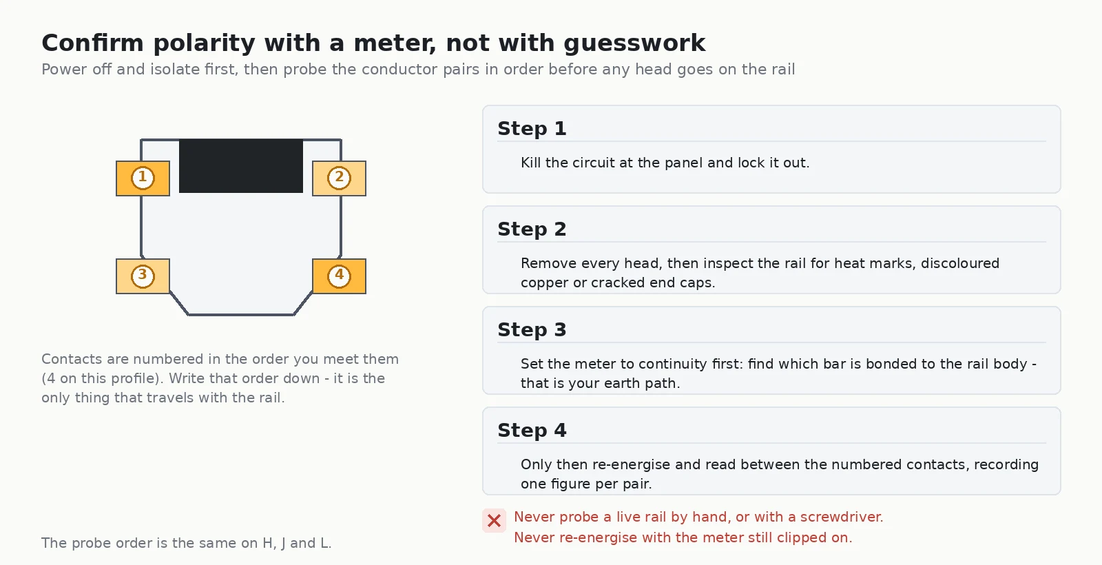
The method matters more than the meter. Kill the circuit at the panel and lock it out. Remove every head and inspect the rail for heat marks, discoloured copper, pitted contact surfaces or cracked end caps — these are the findings that change the project from a head swap into a rail replacement. Set the meter to continuity first and find which bar is bonded to the rail body; that is your earth path, and it should be verified before anything is re-energised. Only then re-energise and read between the numbered contacts, recording one figure per pair against the number you wrote down.
Number the contacts in a fixed order the first time you open a rail, and photograph the section. That record is the only thing that travels with the installation — the label on the back of the rail usually will not survive the next repaint.
Why adapters do not interchange
A head adapter seats when three things line up at once: the slot width, the slot depth and the contact spacing. Across H, J and L all three differ.
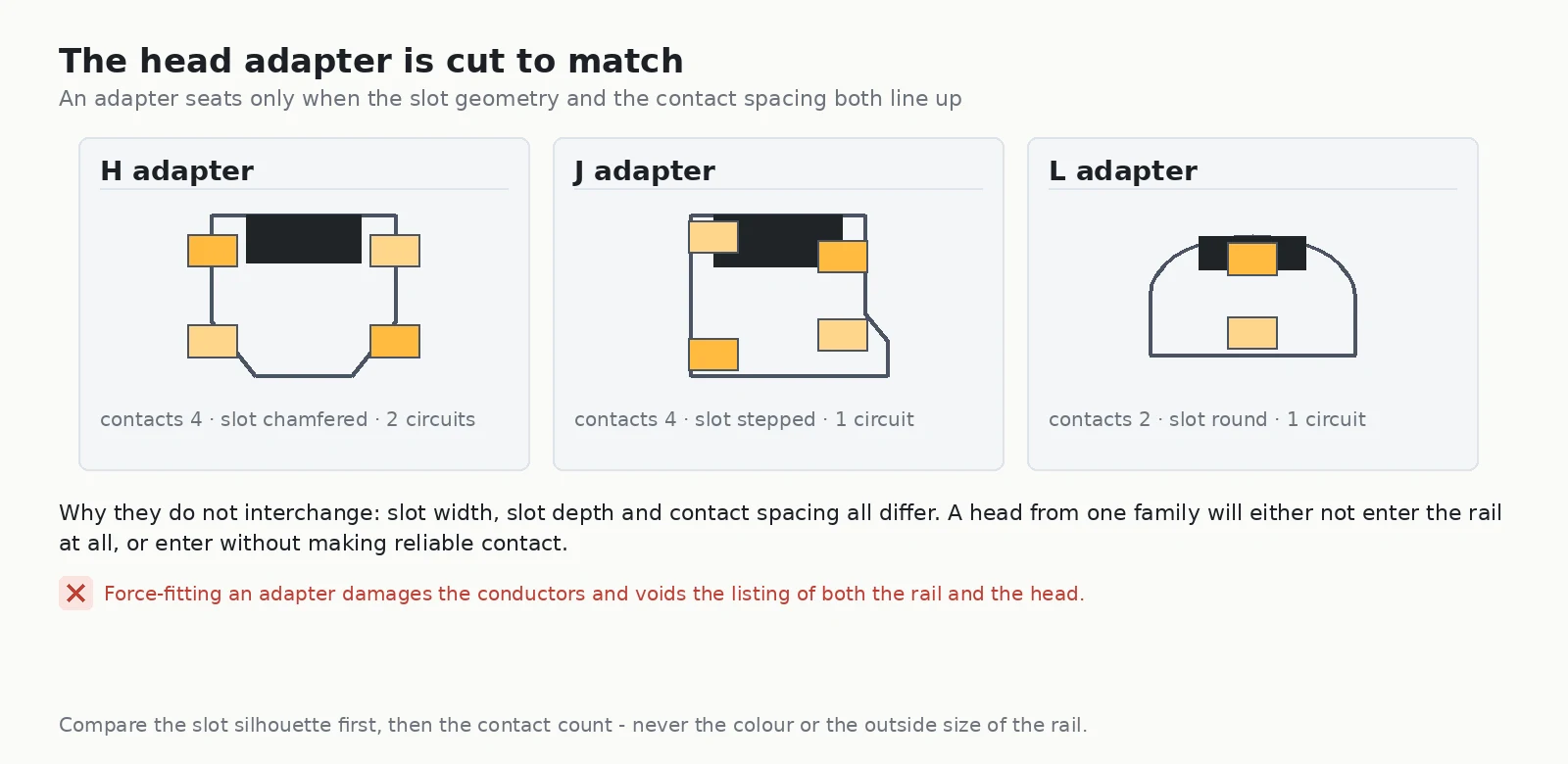
Force-fitting an adapter is the failure mode to avoid, because it can appear to work. The head rotates into place, the lamp lights, and the installation is signed off — with contact pressure that is wrong and a joint that runs warm. When it fails, it fails in the ceiling rather than at handover. Forcing an adapter also damages the conductors and voids the listing of both the rail and the head.
Keep the rail, or replace it?
Both routes are legitimate. The decision comes from the geometry, not from preference.
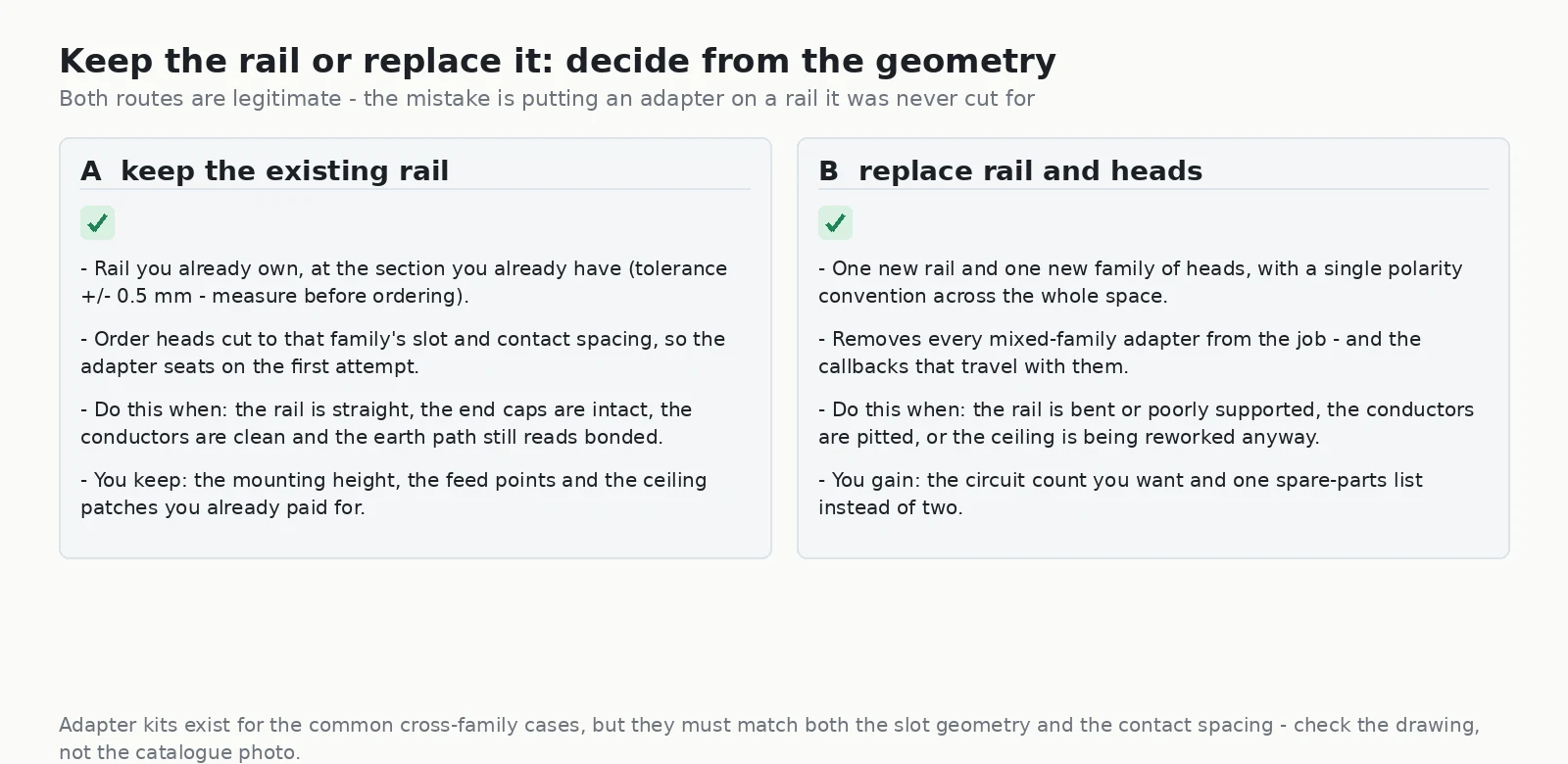
Keep the rail when it is straight, the end caps are intact, the conductors are clean and the earth path still reads bonded. You keep the mounting height, the feed points and the ceiling patches you already paid for, and the only new part is a head cut to that family’s slot and contact spacing.
Replace rail and heads when the rail is bent or poorly supported, when the conductors are pitted, or when the ceiling is being reworked anyway. You gain a single polarity convention across the whole space, the circuit count you actually want, and one spare-parts list instead of two.
Three ways identification goes wrong
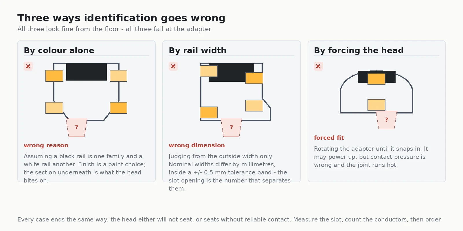
- By colour alone. Assuming a black rail is one family and a white rail another. Finish is a paint choice; the section underneath is what the head bites on.
- By rail width. Judging from the outside width only. Nominal widths differ by a few millimetres, well inside a normal tolerance band — the slot opening and the conductor offsets are the numbers that separate the families.
- By forcing the head. Rotating the adapter until it snaps in. It may power up, but contact pressure is wrong and the joint runs hot.
Specifying new track: use the geometry, not the letter
If you are buying new rather than identifying old, the letters are less useful than the underlying specification, because modern systems are engineered around clean-sheet geometry rather than the legacy profiles. What matters is that the rail, the heads and the accessories come from one system, so the slot, the conductors and the polarity convention are guaranteed to match.
Our own track systems are built this way: a single circuit profile for straightforward runs, a three-circuit profile when one rail has to carry separately switched zones, and a three-circuit DALI version where the zones are addressed digitally rather than switched. Each is ordered as a complete family, so there is no adapter question to answer on site.
For heads, the choice is driven by the optical job rather than the rail:
- CADIO — 20/25/30 W, 15°/24°/38°/60°, > 100 lm/W, tool-free interchangeable reflectors, honeycomb anti-glare accessory for commercial, gallery and exhibition work.
- VEGA-Standard 30 W — 2581–2978 lm at CRI 90+, 15°/24°/38°/50°, in-track driver for triac, DALI and wireless control, 360° rotation and 90° tilt.
- MEGA 15–20 W — 10°/25°/40°/60°, CRI 90+, snap-on filters that convert one head between spotlight, floodlight and wall wash, CRI 95+ option for museum and gallery work.
- IMAX-Projector 10–20 W — 18°–36° adjustable, four-blade framing for square and triangular beams, UGR < 6.
- MOVIA 30 W — motorised aiming where the ceiling is out of reach.
Where the track is being used as an architectural line rather than a mounting device, our linear lighting systems give a continuous run with modular L, X and T connectors — and the track light range covers the rest of the portfolio.
Site record card
Fill this in at the rail, not from memory. It is the difference between one order and three returns.
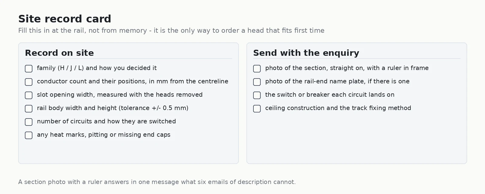
Record on site: the family and how you decided it; the conductor count and their positions in millimetres from the centreline; the slot opening width with the heads removed; the rail body width and height; the number of circuits and how they are switched; and any heat marks, pitting or missing end caps.
Send with the enquiry: a photograph of the section taken straight on with a ruler in frame; a photograph of any name plate at the rail end; the switch or breaker each circuit lands on; and the ceiling construction with the track fixing method.
FAQ
Are H, J and L track interchangeable?
No. Each family has its own slot geometry, conductor count and conductor spacing, so a head from one family will not seat on another family’s rail and can fail to make reliable contact. Cross-family adapter kits exist for some combinations, but they must be matched to both the slot geometry and the contact spacing of the rail in front of you.
What is the fastest way to tell an H track from a J track?
Remove a head and look at the conductor layout. If the bars form mirrored pairs on both sides of the spine and the section is visibly symmetric, it is an H. If the section is lopsided, with conductor sets on opposite sides sitting at different depths, it is a J.
How do I identify an L track?
Two conductors stacked vertically on one centreline, with no lateral offset from the centre, and a noticeably flatter, wider section with round shoulders. If you measure the conductor offset from the centreline and get zero on both bars, it is an L.
Can I just measure the width of the rail?
No. Nominal widths across the families differ by only a few millimetres, which is inside a normal extrusion tolerance band, and repainting or a powder coat can add to that. Measure the slot opening with the heads removed and the conductor offsets instead.
Do I need an electrician to check which bar is which?
Polarity confirmation involves working on a circuit that has been energised, so it should be done by a qualified person. The sequence is: isolate and lock out at the panel, remove the heads, inspect the rail, verify the earth path on continuity, and only then re-energise and read between the numbered contacts.
Is it worth replacing a rail I cannot identify?
It depends on condition, not on the letter. Keep the rail when it is straight, the end caps are intact, the conductors are clean and the earth path reads bonded — you only need heads cut to that family. Replace it when the rail is bent or poorly supported, the conductors are pitted, or the ceiling is being reworked anyway.
What should I send to get the right head first time?
A photograph of the cross section taken straight on with a ruler in the frame, plus the conductor count, the slot opening width and the number of circuits. That single photograph typically settles the order without any further back-and-forth.
Before you order
Identification is a ten-minute job with a torch and a tape, and it decides everything downstream: which head, which adapter, whether the rail stays. Do it in the order above — proportions, spine, conductor count, conductor position, then confirm with the slot opening — and the order goes out once.
If you are mid-project and would rather send the section to us than work it out alone, talk to the Encore specification team with the photograph and the four measurements. If the project is going out to tender, our track lighting RFQ guide sets out everything a supplier needs.
Further reading: IES recommended practice for lighting systems and the U.S. Department of Energy solid-state lighting standards.